Aftermarket activity

Industrialization of innovative projects

Back to the list

Crankshaft sensors

The advent of the autonomous car has highlighted the fundamental importance of having good sensors. That being said, we have long been committed to providing effective – and reliable – sensors to our customers. So whether you are looking for engine and transmission sensors, or for comfort and safety – not to mention emissions and e-mobility – you should definitely take a look at our range.

Back to the list
Crankshaft
sensors

Also known as “TDC sensor” or “rpm sensor”, this sensor measures the speed and position of the crankshaft. It is often (but not always) located in the immediate vicinity of the flywheel, acting as – or hosting – the rotating target.

In practice, it is the very rotation of this target, positioned in front of the sensor, that generates variations in magnetic flux. These are then measured precisely, to enable the ECU to interpret the crankshaft’s rotation speed and position. Thanks to an advanced algorithm, it deduces the most opportune moment for injection and adjustment of the ignition advance point. The ECU then uses this information to determine a crucial moment for fuel injection.

As the European market leader in engine management sensors, our Group has acquired an extensive expertise in both technologies. Choosing our camshaft sensors therefore means choosing the quality of an Original Equipment Manufacturer (OEM) recognised for its expertise by the world’s leading manufacturers.

Technologies
Technical information
Frequently asked questions
Resources
Technologies

INDUCTIVE EFFECT

Inductive sensors (also called VRS) consist of a coil mounted on a metal rod and a permanent magnet. The sensor is mounted facing the toothed (or phonic) road. The magnetic flux that occurs between the teeth (or valleys) of the wheel induces a sinusoidal output voltage, proportional to the change in speed detected by the sensor. The voltage therefore varies according to the speed of the motor and the distance from the sensor to the gearwheel, both in frequency and amplitude.

HALL EFFECT

Hall effect sensors consist of a semi-conductive cell coupled to an electronic circuit (protecting the sensor from possible voltage peaks) and a permanent magnet. The operating principle is based on the so-called “Hall effect”; i.e., an electric current flowing through a conductor in a magnetic field and creating a so-called perpendicular voltage. The response obtained from the sensor is a square wave signal – and not sinusoidal, as with VRS – which is proportional to the variations detected.

Technical information

SYMPTOMS

The following symptoms are frequently associated with a crankshaft sensor failure:

  • Fault signal on the dashboard (engine light);
  • Appearance of numerous jerks;
  • Slow and difficult or impossible vehicle start-up;
  • Incorrect data on the rpm counter;
  • Untimely stalling;
  • Appearance of noises coming from the engine.


DIAGNOSIS PROCEDURE

First and foremost, you need to visually inspect the crankshaft sensor to determine the presence of a fault. It is therefore strongly recommended to check the following:

  • The sensor itself (presence of dirt);
  • The wire set that connects it to the ECU (damage);
  • The space between the sensor and the flywheel teeth (must not exceed 1mm).

For an inductive sensor (VRS), you should check the resistance with a multimeter; it should be between 250 and 1000 Ω depending on the manufacturer. If the displayed value is zero, then there is a short circuit.

For a Hall Effect sensor, it is necessary to have an oscilloscope to measure the electrical signal. You will first need to make sure you have disconnected the connector on the ECU side. Then, check that there is a signal by starting the engine. The value measured should be between 250 mV and 1 V.

If the previous tests are not conclusive, you will probably need to replace your crankshaft sensor.

CAUSES OF FAILURE

It is possible that a crankshaft sensor is no longer working due to:

  • Excessive heat which can melt the sensor’s plastic covering and damage the component;
  • Wear and tear over time;
  • Damage to the sensor connection wires;
  • Failure of the wheel and pins.

INSTALLATION INSTRUCTIONS

To ensure a quick and efficient installation, you must refer to the following instructions:

  1. Locate the sensor in question, next to the flywheel – accessible after removing the engine cover.
  2. Release the sensor locking clip(s) towards the rear. Then press the tab to disconnect the sensor.
  3. Next, unscrew the sensor with a socket spanner of the same diameter as the sensor screw.
  4. Position the new sensor on the head cover and press firmly to install it securely.
  5. Fit the screw and tighten it with your socket spanner – if you use a torque spanner, make sure you respect the torque recommended by the manufacturer (around 9Nm, as a general rule).
  6. Reconnect the connector and replace the motor cover.

INSTALLATION TIPS

As the crankshaft sensor is essential to the correct operation of the engine, it is important to follow a certain number of recommendations when replacing it:

  • Pay attention to the position of the cable when fitting the new sensor.;
  • Also replace the O-ring, do not use the old one;
  • The use of magnetic tools can lead to demagnetization problems of the targets associated with the camshaft sensors;
  • The air gap (1 mm for optimal detection) must be respected, otherwise the sensor will be damaged, or the signal will be erroneous or even absent.

PREVENTIVE INFORMATION

The above items are provided for information purposes only. They do not replace the advice of a qualified technician or mechanic. We strongly recommend that you consult a professional if you are unsure of what to do. Otherwise, we cannot accept responsibility for any damage to your vehicle.

Frequently asked questions
What symptoms should I look out for?

When a camshaft sensor fails, the engine light (orange) comes on, idling becomes erratic and performance is reduced – on some vehicles a “limp mode” is activated, allowing you to drive home or to the nearest garage at low speed. Sometimes, the vehicle simply refuses to start or stalls unexpectedly. Finally, and concurrently, we can observe increased fuel consumption and pollutant emissions.

How to identify the fault?

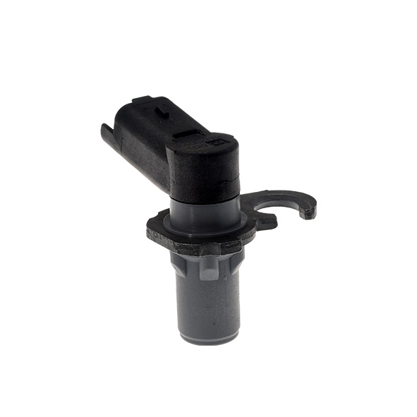
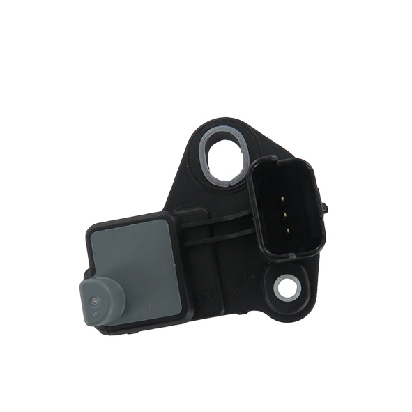
Firstly, we strongly advise you to visually check the crankshaft sensor; i.e., its connector (poor connection or loosening of the connector), and its wiring (presence of damaged wires).

Secondly, you can test your sensor’s correct functioning by checking its resistance. However, the tests to be conducted will depend on the technology of the sensor.

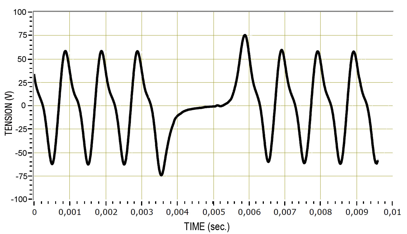
For an inductive sensor (VRS), you will need to check the resistance with a multimeter – it should be between 300 and 900 Ω, depending on the manufacturer. You can also check the continuity of the electrical wires linking the sensor to the ECU (=0 Ω).

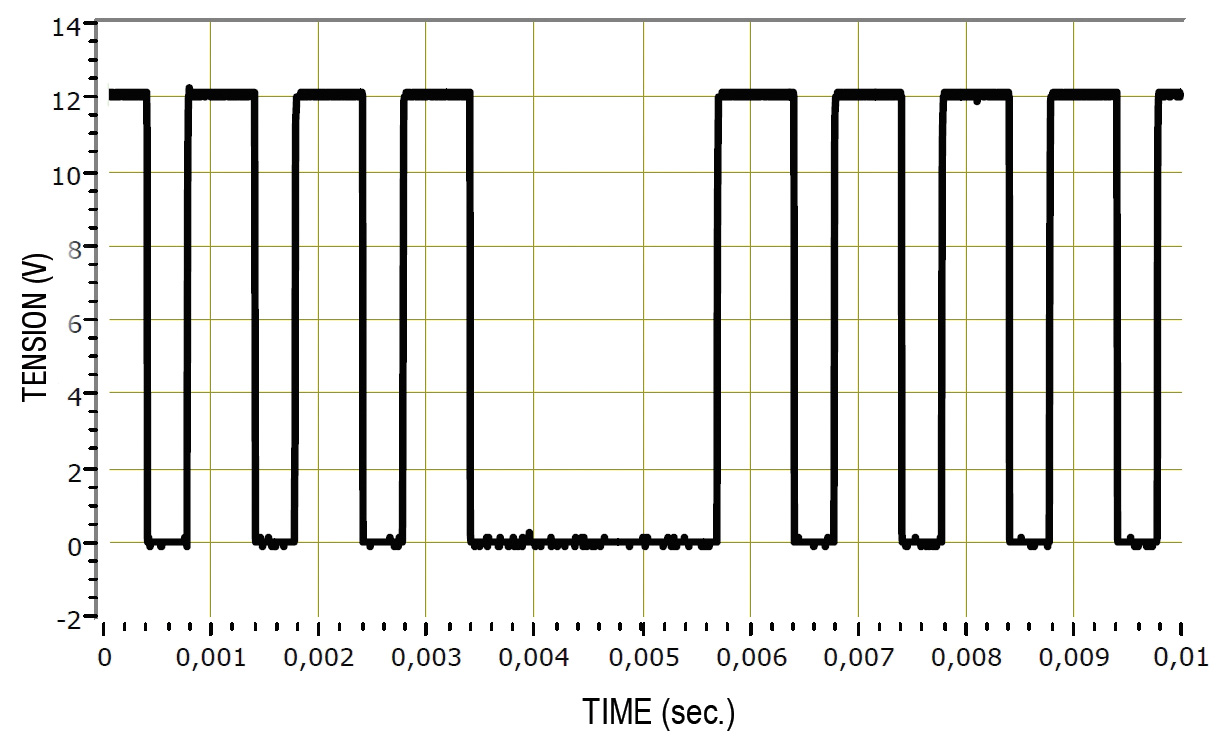
For a Hall Effect sensor, you will need an oscilloscope to measure the electrical signal. Make sure you have disconnected the ECU side connector and then check that there is a signal present by starting the engine.

If the above tests are not conclusive, then it would appear that you need to replace your vehicle’s crankshaft sensor.

Why does my crankshaft sensor need replacing?

Although automotive sensors are built to a very high standard, they do not last forever and there are a number of reasons why they may need to be replaced, including a faulty power supply, or external damage (such as metal debris). There is also internal damage due to strong vibrations – for example when the exhaust line is not sufficiently secured.

What are the installation instructions?

We recommend the following steps to replace your crankshaft sensor as efficiently as possible and to limit possible mistakes.

  1. Locate the sensor in question next to the flywheel – accessible after removing the engine cover.
  2. Release the sensor locking clip(s) towards the rear. Then press the tab to disconnect the sensor.
  3. Next, unscrew the sensor with a socket spanner of the same diameter as the sensor screw.
  4. Position the new sensor on the head cover and press firmly to install it securely.
  5. Fit the screw and tighten it with your socket spanner – if you use a torque spanner, make sure you observe the torque recommended by the manufacturer (usually around 9Nm).
  6. Reconnect the connector and replace the motor cover.
What tips should I use to extend the life of my crankshaft sensor?

In order to extend your crankshaft sensor’s durability, and as a subsidiary of the world’s leading camshaft and crankshaft sensor group for over 85 years now, we strongly advise you to observe the following installation recommendations:

  • Driving with a defective sensor can damage other vehicle parts, especially the catalytic converter;
  • Respect the tightening torque recommended by the manufacturers: 9Nm;
  • The use of magnetic tools can lead to demagnetization problems of the targets associated with the crankshaft sensor;
  • The air gap (1mm for optimal detection) must be respected, otherwise the sensor may be damaged or the signal may be erroneous or absent.
Resources
You can download the best-sellers associated with this product family below.
Best-sellers
Find out more about our top 8 sellers for the European market.
Download