Aftermarket activity

Industrialization of innovative projects

Back to the list

Camshaft sensors

The advent of the autonomous car has highlighted the fundamental importance of having good sensors. That being said, we have long been committed to providing effective – and reliable – sensors to our customers. So whether you are looking for engine and transmission sensors, or for comfort and safety – not to mention emissions and e-mobility – you should definitely take a look at our range.

Back to the list
Camshaft
sensors

In combination with the crankshaft sensor, it allows the ECU to identify the position of the first cylinder’s piston, but more importantly its combustion cycle. This allows the engine management system to inject fuel into the right cylinders at the right time – ultimately to achieve better engine efficiency.

Magnetic flux variations are detected by the gear (or ferromagnetic target) positioned in front of the camshaft sensor – the same principle actually applies to the crankshaft sensor. These two sensors then convert the variations into electrical signals and send them to the ECU, which interprets them to determine the amount of fuel to be injected into the intake valves, as mentioned above.

As the European market leader in engine management sensors, our Group has acquired an extensive expertise in both technologies. Choosing our camshaft sensors therefore means choosing the quality of an Original Equipment Manufacturer (OEM) recognised for its expertise by the world’s leading manufacturers.

Technologies
Technical information
Frequently asked questions
Resources
Technologies

INDUCTIVE EFFECT

Inductive sensors (also called VRS) consist of a coil mounted on a metal rod and a permanent magnet. The sensor is mounted opposite the gearwheel (or phonic wheel). The magnetic flux that occurs between the teeth (or valleys) of the wheel induces a sinusoidal output voltage, proportional to the change in speed detected by the sensor. The voltage therefore varies according to the speed of the motor and the distance from the sensor to the gearwheel, both in frequency and amplitude.

HALL EFFECT

Hall effect sensors consist of a semi-conductive cell coupled to an electronic circuit (protecting the sensor from possible voltage peaks) and a permanent magnet. The operating principle is based on the so-called “Hall effect”; i.e., an electric current flowing through a conductor in a magnetic field and creating a so-called perpendicular voltage. The response obtained from the sensor is a square wave signal – and not sinusoidal, as with VRS – which is proportional to the variations detected.

Technical information

SYMPTOMS

The following symptoms are frequently associated with a camshaft sensor failure:

  • Fault signal on the dashboard (engine light);
  • Loss of engine power;
  • Slow and difficult or impossible vehicle start-up;
  • Increased fuel consumption;
  • Untimely stalling;
  • Transmission problems.

DIAGNOSTIC PROCEDURE

First and foremost, you need to visually inspect the camshaft sensor to determine the presence of a fault. It is therefore strongly recommended to check the following:

  • The wires (visible damage and/or bad connections);
  • The electrical connector (loose connections).

You can also check that the sensor is working properly by ensuring that the resistance is correct. The tests will differ depending on the sensor technology.

For an inductive sensor (VRS), you should check the resistance with a multimeter; it should be between 250 and 1000 Ω depending on the manufacturer. If the displayed value is zero, then there is a short circuit.

For a Hall Effect sensor, it is necessary to have an oscilloscope to measure the electrical signal. You will first need to make sure you have disconnected the connector on the ECU side. Then, check that there is a signal by starting the engine. The value measured should be between 250 mV and 1 V.

If the previous tests are not conclusive, your will probably need to replace your camshaft sensor.

CAUSES OF FAILURE

It is possible that a camshaft sensor is no longer working due to:

  • Faulty power supply;
  • External damage caused by metal debris;
  • Time-related wear and tear and/or internal damage due to the engine environment (heat, vibrations).

INSTALLATION INSTRUCTIONS

To ensure a quick and efficient installation, you must refer to the following instructions:

  1. Locate the sensor in question at the level of the cylinder head cover – it is accessible after removing the engine cover.
  2. Release the sensor locking clip(s) towards the rear. Then press the tab to disconnect the sensor.
  3. Next, unscrew the sensor with a socket spanner of the same diameter as the sensor screw.
  4. Position the new sensor on the head cover and press firmly to install it securely.
  5. Fit the screw and tighten it with your socket spanner – if you use a torque spanner, make sure you respect the torque recommended by the manufacturer (around 9Nm, as a general rule).
  6. Reconnect the connector and replace the motor cover.

INSTALLATION TIPS

As the camshaft sensor is essential to the correct operation of the engine, it is important to follow a certain number of recommendations when replacing it:

  • Driving with a defective sensor can damage other vehicle parts, especially the catalytic converter;
  • Respect the tightening torque recommended by the manufacturers: 9Nm;
  • The use of magnetic tools can lead to demagnetization problems of the targets associated with the camshaft sensor;
  • The air gap (1 mm for optimal detection) must be respected, otherwise the sensor will be damaged, or the signal will be erroneous or even absent.

PREVENTIVE INFORMATION

The above items are provided for information purposes only. They do not replace the advice of a qualified technician or mechanic. We strongly recommend that you consult a professional if you are unsure of what to do. Otherwise, we cannot accept responsibility for any damage to your vehicle.

Frequently asked questions
What symptoms should I look out for?

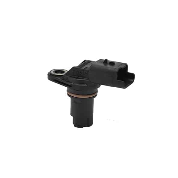
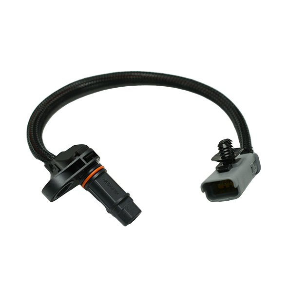
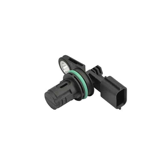
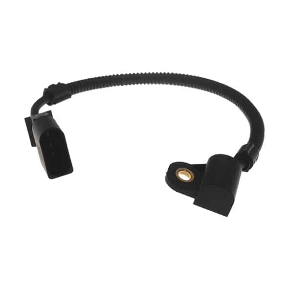
If you notice an engine light (orange light) lighting up on your dashboard, then it is possible that the camshaft sensor is in a critical condition. Chances are that the vehicle is losing power (going into “limp mode”), allowing you to drive home or to the nearest garage at a slow pace. But it is also possible that your vehicle simply will not start. An increase in fuel consumption, as well as an increase in exhaust emissions (CO, NOx and HC) are further symptoms of a camshaft sensor failure.

How to identify the fault?

Firstly, we strongly advise you to visually check the camshaft sensor; i.e., its connector (poor connection or loosening of the connector), and its wiring (presence of damaged wires).

Secondly, you can test your sensor’s correct functioning by checking its resistance. However, the tests to be conducted will depend on the technology of the sensor.

For an inductive sensor (VRS), you will need to check the resistance with a multimeter – it should be between 300 and 900 Ω, depending on the manufacturer. You can also check the continuity of the electrical wires linking the sensor to the ECU (=0 Ω).

For a Hall Effect sensor, you will need an oscilloscope to measure the electrical signal. Make sure you have disconnected the ECU side connector and then check that there is a signal present by starting the engine.

If the above tests do not prove conclusive, then it would appear that you need to replace the camshaft sensor in your vehicle.

Why does my camshaft sensor need replacing?

There are many reasons why the camshaft sensor may be failing. These include a faulty power supply, or external damage (e.g., from metal debris). Although automotive sensors meet strict standards, they do not last forever and their environment does not help. In fact, the sensor may simply need to be replaced because it is exposed to severe conditions (vibration, high heat).

What are the installation instructions?

We recommend the following steps to replace your camshaft sensor as efficiently as possible and to limit possible mistakes:

  1. Locate the sensor in question at the level of the cylinder head cover – it is accessible after removing the engine cover.
  2. Release the sensor locking clip(s) towards the rear. Then press the tab to disconnect the sensor.
  3. Next, unscrew the sensor with a socket spanner of the same diameter as the sensor screw.
  4. Position the new sensor on the head cover and press firmly to install it securely.
  5. Fit the screw and tighten it with your socket spanner – if you use a torque spanner, make sure you respect the torque recommended by the manufacturer (around 9Nm, as a general rule).
  6. Reconnect the connector and replace the motor cover.
What tips should I use to extend the life of my camshaft sensor?

In order to extend your camshaft sensor’s durability and as a subsidiary of a world leader in camshaft and crankshaft sensors for over 85 years, we strongly advise you to observe the following installation recommendations:

  • Driving with a defective sensor can damage other vehicle parts, especially the catalytic converter;
  • Respect the tightening torque recommended by the manufacturers: 9Nm;
  • The use of magnetic tools can lead to demagnetization problems of the targets associated with the camshaft sensor;
  • The air gap (1mm for optimal detection) must be respected, otherwise the sensor will be damaged, or the signal will be erroneous or absent.
Resources
You can download the best-sellers associated with this product family below.
Best-sellers
Find out more about our top 8 sellers for the European market.
Download